Observing Frequencies
The three radio-frequency bands available in all modes for observing are:
- L-Band (1.25 -1.75 GHz),
- C-Band (4.3 - 7.5 GHz) and
- K-Band (19 - 25 GHz).
Proposals can include any of these bands and may also request inclusion of the 76 metre Lovell telescope (except at K-Band),
although this requires a demonstration of its necessity due to its more limited availability.
e-MERLIN Imaging Mode
This is the standard observing mode for e-MERLIN, and the most requested by observers around the world, correlated in real time at Jodrell Bank Observatory producing sub-arcsecond resolution images with micro-Jansky sensitivities. It is available in all three observing bands: L, C and K. Typical specifications for expected performance for a standard phase-referenced observation are listed in the following table. It assumes a standard 7 minute target and 3 minute phase-calibrator cadence throughout the integration period, with typical fractions of flagged data due to sporadic RFI etc.
| L-Band (1.5 GHz) |
C-Band (5 GHz) |
K-Band (22 GHz) |
Comments | |
|---|---|---|---|---|
| Resolution (arcsec) | 0.2" | 0.05" | 0.02" | Natural weighting at central frequency |
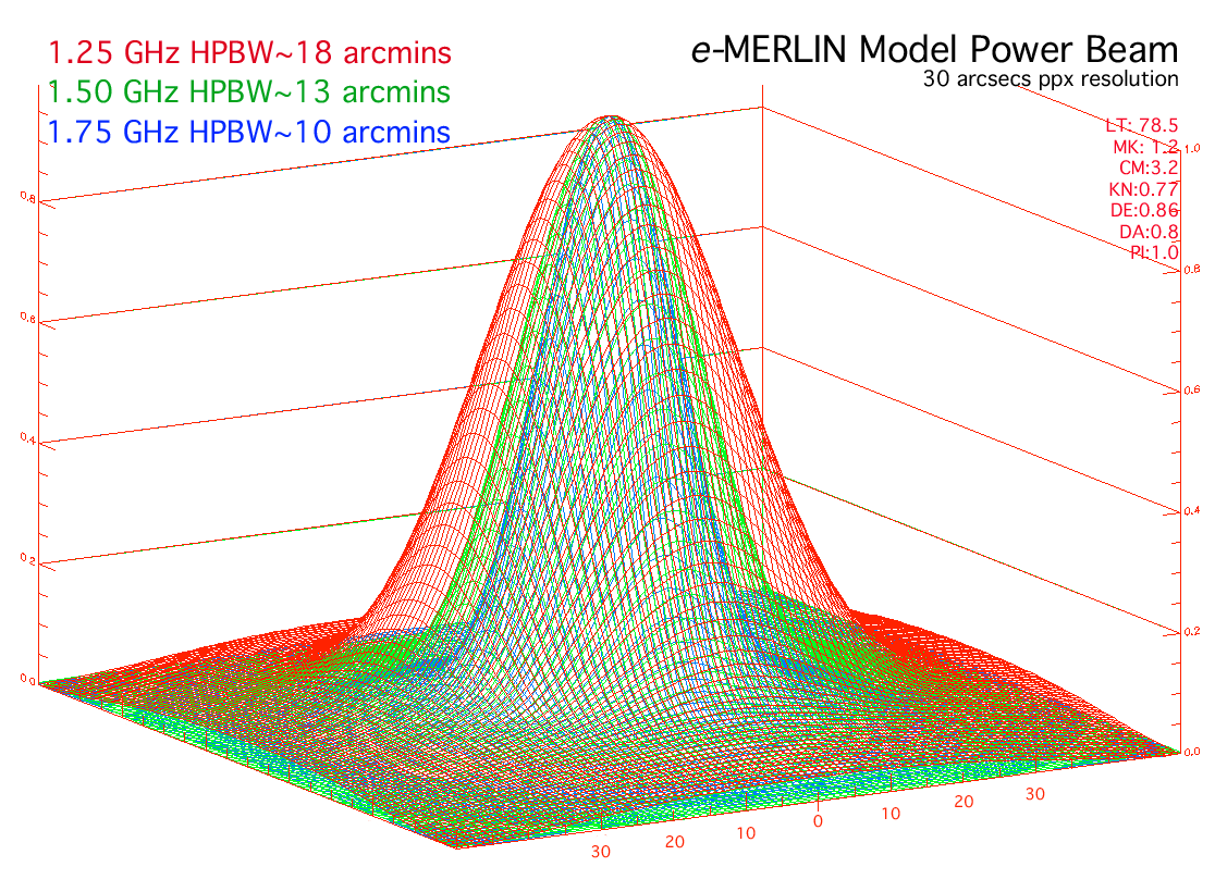
| Field of View (arcmin) | 30' | 7' | 2' | WITHOUT the Lovell telescope |
| Freq. Range (GHz) | 1.25 - 1.75 | 4.3 - 7.5 | 19 - 25 | Max bandwidth 512 MHz |
| Sensitivity in 12-hour observation | 24 μJy/b | 16 μJy/b | ~120 μJy/b | Measured WITHOUT the Lovell Telescope |
| Sensitivity in 12-hour observation | 12 μJy/b | 10 μJy/b | - | WITH the Lovell Telescope |
| Astrometric performance (milli-arcsec) | ~2 | ~1 | ~2 | With respect to the ICRF (typical 3-deg target-calibrator separation using VLBA Calibrator Survey) |
Note that the inclusion of the 76 m diameter Lovell telescope approximately doubles the sensitivity of the array (except at K-Band), however, due to its narrower beam-width, the field of view is approximately halved, depending on the weighting scheme adopted in imaging.
Continuum Correlator Settings
The default correlator set up is for optimal band coverage, dividing its 512 MHz of bandwidth into narrow enough channels to minimise bandwidth smearing (<10%) at the edge of full field-of-view images. Similarly, correlation averaging time is defaulted to 1 second to minimise time-smearing. Each band is divided into contiguous spectral windows (SPWs or sub-bands) within the correlator, with each spectral window divided into 512 equally spaced channels. Hence, to maintain minimum smearing, L-Band is divided into 8 spectral windows, whereas C and K bands are divided into 4 spectral windows.
| Bandwidth (MHz) | Bits sample /corr | SPWs | SPW bandwidth (MHz) | No. of Pols | No. of Chans (/pol, /spw) |
Channel width (kHz) | FOV (arcmin) |
|---|
| Continuum Mode (L-Band): |
| 512 | 8/7 | 8 | 64 | 4 | 512 | 125 | 37.3 |
| 512 | 8/7 | 8 | 64 | 2 | 1024 | 62.5 | 74.6 |
| Continuum Mode (C-Band, K-Band): |
| 512 | 8/7 | 4 | 128 | 4 | 512 | 250 | 18.6 |
| 512 | 8/7 | 4 | 128 | 2 | 1024 | 125 | 37.3 |
Spectral-Line Correlator Settings
In addition to these continuum bands, extra spectral windows can be placed within continuum spectral windows allowing high frequency resolution sub-bands to be overlaid, ideal for spectral-line observations. Hence continuum observations can be observed simultaneously with spectral-line measurements.

The above figure illustrates 8 continuum spectral windows (SPWs), placed across L-band (1.25 - 1.75 GHz), with 5 additional high-frequency-resolution spectral-line windows covering frequencies at which spectral lines are expected. These are particularly useful for observing MASER sources.
Spectral-line mode correlator capabilities are described in the table below, illustrating that additional SPWs must be divided into continuum windows as an integer fraction of a power of 2. The bandwidth is divided by factors of 2n into spectral-line windows which can be the same width as one of the continuum SPWs, or smaller by a factor of 2n. However, spectral-line windows cannot overlap continuum SPW edges.
| Bandwidth (MHz) | Bits smpl/cor | No. of SPWs | SPW bandwidth (MHz) | No. of Pols | No. of Chans (/pol, /spw) |
Channel width (kHz) | FOV (arcmin) |
|---|
| Spectral-line modes (maximum no-recirculation, 4-bit correlation): |
| 256 | 3/4 | 4 | 64 | 4 | 512 | 125 | (2) |
| 128 | 3/4 | 4 | 32 | 4 | 512 | 62.5 | |
| ↓ | ↓ | ↓ | ↓ | ↓ | ↓ | ↓ | |
| 2 | 3/4 | 4 | 0.5 | 4 | 512 | 0.976563 | |
| 1 | 3/4 | 4 | 0.25 | 4 | 512 | 0.488281 |
In most cases of Direct Correlator Imaging, it is normal to accept default correlator settings for continuum windows, and then specify the positions of the spectral-line windows on-top of them. You can simply specify the lines required in your proposal and let the e-MERLIN scheduling team determine the appropriate placement and any necessary Doppler VLSR correction as these depend on the exact time of observation.
Spectral-Line Rest Frequencies
- HI 1420.406 MHz
- OH 1612.231 1665.402 1667.359 1720.530 MHz
- OH 4650.656, (4660.242), 4765.562 MHz
- OH (6016.746), 6030.747, 6035.092, 6049.084 MHz
- H2CO 4829.641 - 4829.671 MHz
- CH3OH 6668.619 MHz
- H2O 22.235 GHz
- NH3 23.694, 23.723, 23.87 GHz
L-Band
C-Band
K-Band
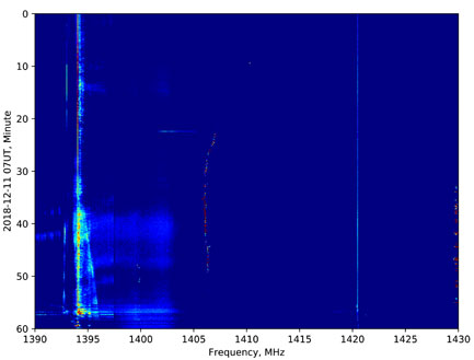
Frequencies affected by RF interference include 1450-1520, 1310-1340 and around 1390 MHz. These frequencies are not always unusable but please consult e-MERLIN support if you wish to observe red-shifted lines within these ranges.
The actual spectral resolution may be broader if Hanning or other smoothing is applied. The sensitivities below are given for the optimum central part of the band and will degrade towards the band edges. Bright emission in narrow channels will be more dynamic-range limited. About 10% of edge channels within each band may have lower sensitivity if the SPWs are not placed optimally.
L-band Spectral Line Configurations
| spw width | Channel separation | 1σrms 12 hr sensitivity per channel | |||||
|---|---|---|---|---|---|---|---|
| (MHz) | (km/s) | (kHz) | (km/s) | with Lovell | no Lovell | ||
| (mJy/bm) | (1000 K) | (mJy/bm) | (1000 K) | ||||
| 32 | 6760 | 62.5 | 13.2 | 0.43 | 6.4 | 0.86 | 13 |
| 16 | 3380 | 31.25 | 6.6 | 0.61 | 9.1 | 1.2 | 18 |
| 8 | 1690 | 15.625 | 3.3 | 0.86 | 13 | 1.7 | 26 |
| 4 | 845 | 7.7125 | 1.7 | 1.2 | 18 | 2.4 | 36 |
| 2 | 423 | 3.9063 | 0.8 | 1.7 | 26 | 3.4 | 52 |
| 1 | 211 | 1.9531 | 0.4 | 2.4 | 36 | 4.9 | 73 |
| 0.5 | 106 | 0.9766 | 0.2 | 3.4 | 52 | 6.9 | 103 |
| 0.25 | 52.8 | 0.4882 | 0.1 | 4.9 | 73 | 9.7 | 146 |
C-band Spectral Line Configurations
| spw width | Channel separation | 1σrms 12 hr sensitivity per channel | |||||
|---|---|---|---|---|---|---|---|
| (MHz) | (km/s) | (kHz) | (km/s) | with Lovell | no Lovell | ||
| (mJy/bm) | (1000 K) | (mJy/bm) | (1000 K) | ||||
| 128 | 6400 | 250 | 12.5 | 0.25 | 3.8 | 0.47 | 7.0 |
| 64 | 3400 | 125 | 6.3 | 0.35 | 5.3 | 0.66 | 9.9 |
| 32 | 1600 | 62.5 | 3.1 | 0.50 | 7.5 | 0.93 | 14 |
| 16 | 800 | 31.25 | 1.6 | 0.71 | 11 | 1.3 | 20 |
| 8 | 400 | 15.625 | 0.8 | 1.0 | 15 | 1.9 | 28 |
| 4 | 200 | 7.7125 | 0.4 | 1.4 | 21 | 2.6 | 39 |
| 2 | 100 | 3.9063 | 0.2 | 2.0 | 30 | 3.7 | 56 |
| 1 | 50 | 1.9531 | 0.1 | 2.8 | 43 | 5.3 | 79 |
| 0.5 | 25 | 0.9766 | 0.05 | 4.0 | 60 | 7.4 | 112 |
| 0.25 | 12.5 | 0.4882 | 0.03 | 5.7 | 85 | 11 | 158 |
Example of Spectral Line Window Placement
In the following example we wish to observe HI and OH absorption lines for a source placed at redshift z=0.09. Suppose the target has HI absorption of up to 10 mJy per e-MERLIN beam at redshift ~0.09, and spans about 500 km/s, against continuum of up to 100 mJy/beam. A spectral resolution better than 10 km/s is needed. The observing frequency for the 21-cm HI line is about 1303.1 MHz. A 16-MHz SPW in 512 channels will give about 7 km/s channel separation and a 3-sigma sensitivity of 1.4 mJy/beam per channel in 24 hr on target with the Lovell. The total velocity span in this SPW is ~3400 km/s. We centre this, slightly asymmetrically, on 1301 MHz, which still gives over 1300 km/s on the closer side of the HI line.
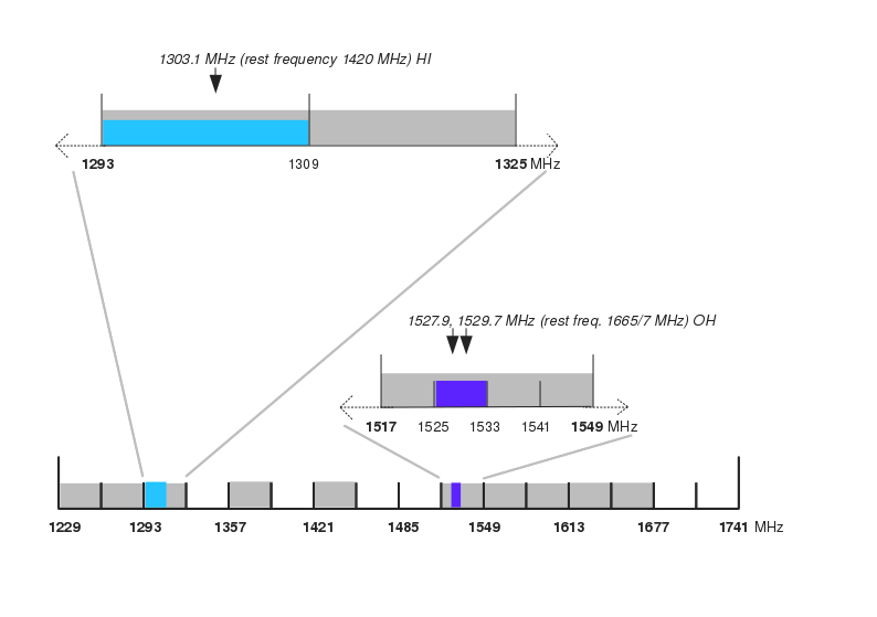
This is to allow the OH 1665- and 1667-MHz lines to be fitted in optimally. At this redshift, they have observing frequencies of about 1527.9 and 1529.7 MHz, respectively. A spw of 8 MHz centred at observing frequency 1529 MHz will give a velocity span of more than 1500 km/s with a channel separation of 3 km/s, sensitivity 2 mJy/beam under the same conditions as the HI. The velocity width for each line is at least 500 km/s both above and below the central velocity.
The remaining spectral windows will normally be used for continuum.VDIF Mode for VLBI & Pulsar Observations
For uncorrelated observations, the correlator is placed into 2-bit VDIF Mode in which it resamples the data into VDIF format at the full temporal resolution of the samplers. This enables raw uncorrelated data to be stored for subsequent processing e.g. later correlation or time-stream analysis. As well as using this mode for Pulsar observing, this is how e-MERLIN is used within the European VLBI Network (EVN). All e-MERLIN telescopes can be used within the EVN simultaneously, either with data traditionally stored on disk arrays at JBO, or streamed live with correlation at JIVE using wide-band fibre links.

